
Planar waveguide optical splitter (PLC Splitter) is an integrated waveguide optical power distribution device based on a quartz substrate. Its main function is to split optical signals from one optical fiber to multiple optical fibers. The device is composed of an optical splitter chip and an optical fiber array at both ends. The chip is the core component. The quality of the chip and the split channel directly affect the price of the entire splitter. The chip has one input and N outputs. waveguide. The optical fiber array is located on the upper surface of the chip, and the casing is sealed to form an optical splitter with one input and N output fibers. PLC splitter has excellent optical performance, high stability and high reliability, and can be widely used in PON network. PLC splitters have different package types to meet the application requirements of different scenarios. |
|
Device structure Bare fiber type PLC optical splitters leave bare fibers at all their ends. It is mainly suitable for occasions that are not disassembled frequently, such as cable connector boxes, optical fiber distribution boards, etc.
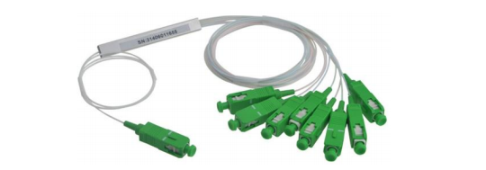
Micro package structure The miniature optical splitter is a miniature steel tube package, which can be divided into pigtails with connectors and pigtails without connectors. Connectors usually come in SC, LC, FC and ST types. Can be installed in fiber optic splice boxes, module boxes, and distribution boxes.
Fan-Out PLC Splitter Fan-out PLC splitter usually uses 0.9mm optical fiber, and a single fiber branch is branched through a bundle of fan-out kits, which can be terminated with different types of connectors. It can be effectively installed in fiber DP boxes, fiber splice boxes or other small terminal boxes. |
 |
ABS Cassette PLC Splitter The splitter packaged in a box is the most used type by operators at present. The ABS package is compact and the application is more flexible. |
 |
Plug-in PLC splitter The plug-in PLC splitter is installed and fixed in the plug-in box, and the interface types are SC/FC/LC, etc. It is mainly suitable for corridors or outdoor light splitting points in FTTH access mode. The commonly used 1X4, 8, 16, 32 and 2X8, 16, 32 PLC splitters are used as plug-in trays for installation in customer-specific enclosures, especially corridor enclosures.
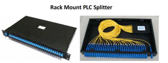
Rack-mounted PLC splitter The rack-mounted optical splitter is designed for standard 19" cabinet installation, which can meet the requirements of high wiring density in data centers or server rooms. Generally, it is packaged in a metal box, which is easy to install in optical fiber projects, and is suitable for PLC splitter devices. Play a good protective role. There are various adapter mounting interfaces such as SC, LC, FC or ST connectors. Rack-mounted |
 |
optical splitters are widely used in FTTX projects, cable TV systems and data communication centers. |
LGX type PLC splitter LGX is an optical splitter packaged in a small metal box, which can be installed in a 19-inch 1U/2U/3U chassis. The input and output end of the pigtail structure can be easily connected to the ODF panel adapter, saving time. LGX's compact and miniature design, plug and play, can be easily installed in fiber distribution boxes, ODF sub-frames, fiber optic terminal boxes and fiber optic cable junction boxes. |
 |
Wall Mounted PLC Splitter The cabinet of the wall-mounted PLC distributor is usually made of ABS material, which provides reliable protection for the direct connection, termination or branch connection of the optical fiber. Double-layer structure, the upper layer is a PLC splitter, and the lower layer is a fiber splice tray. The wall-mounted optical splitter is used in the terminal access link in the FTTH access system to connect and protect optical devices. The wall-mounted optical splitter is suitable for corridors, basements and computer rooms, etc. It is also suitable for outdoor wall-mounted and pole-mounted installations.
Different types of PLC splitters are used to meet the different requirements of OLT and ONT connection and splitting of optical signals on FTTH passive optical networks. HYC can provide various types of splitter boxes and modules, including ABS box PLC splitter, LGX splitter, rack-mounted PLC splitter, etc.
PLC splitter planar optical waveguide splitter process flow The PLC splitter is a research hotspot at home and abroad, and has a good application prospect. However, the packaging of the PLC splitter is a difficult point in the manufacture of the PLC splitter. PLC splitter internal structure. The encapsulation of the PLC splitter refers to aligning each light guide path (ie, the waveguide path) on the planar waveguide splitter with the optical fibers in the optical fiber array one by one, and then sticking them with a specific glue (such as epoxy glue) Technology that comes together. Among them, the alignment accuracy of PLC splitter and fiber array is the key of this technology key.
With the recovery of the optical fiber communication industry and the development of FTTX, the spring of the optical splitter (Splitter) market has also arrived. At present, there are mainly two types of optical splitters: one is a fused taper-type optical fiber splitter produced by using traditional optical passive device fabrication technology (pulled taper coupling method); the other is a planar optical fiber splitter produced by integrated optical technology. Optical waveguide (PLC) splitter. The packaging of the PLC splitter involves the six-dimensional close alignment of the optical fiber array and the optical waveguide, which is difficult. When manual operation is adopted, the disadvantages are low efficiency, poor repeatability, many human factors, and it is difficult to achieve large-scale production.
Real photo of PLC splitter. At the same time, the main disadvantages of the PLC splitter are: (1) The device manufacturing process is complex and the technical threshold is high. At present, the chip is monopolized by several foreign companies, and there are few domestic companies that can package and produce in large quantities.(2) Compared with the fusion taper splitter, the cost is higher, especially in the low channel splitter. PLC splitter packaging technology The packaging process of PLC splitter includes operations such as coupling alignment and bonding. The coupling alignment between the PLC splitter chip and the fiber array can be manual or automatic. The hardware they rely on mainly includes a six-dimensional precision trimming frame, a light source, a power meter, a microscopic observation system, etc., and the most commonly used is automatic alignment, it forms a closed-loop control through optical power feedback, so the docking accuracy and the coupling efficiency of the docking are high. PLC splitter production PLC splitter using semiconductor technology (photolithography, corrosion, development and other technologies) production. The optical waveguide array is located on the upper surface of the chip, and the shunt function is integrated on the chip, that is shunts are realized on one chip: then, the multi-channel fiber arrays at the input end and the output end are coupled at both ends of the chip and to encapsulate. Its internal structure and physical photos are shown in Figure 12, respectively.
The main process of PLC splitter packaging is as follows: (1) Preparation for coupling alignment: first clean the waveguide and then carefully install it on the waveguide frame; then clean the optical fiber, install one end on the precision adjustment frame at the incident end, and install the other end on the precision adjustment frame at the incident end. One end is connected to the light source (the red light source of 6328 microns is connected first, so as to be used for observation during preliminary debugging). (2) Observe the position of the optical fiber and the waveguide at the incident end with the aid of a microscopic observation system, and manually adjust the parallelism and the end face interval between the optical fiber and the waveguide through computer instructions. (3) Turn on the laser light source, according to the X-axis and Y-axis images observed by the microscope system, and use the light spot at the output end of the waveguide to preliminarily judge the coupling and alignment of the optical fiber at the incident end and the waveguide, so as to achieve a good connection between the optical fiber and the waveguide. Lighting effect. (4)When the microscopic observation system observes that the light spot at the output end of the waveguide achieves the desired effect, move the turn on the microscope observation system. (5) Clean the first and eighth channels of the fiber array (FA) at the output end of the waveguide, and use blow up the balloons to dry. Then, the method of step (2) is used to connect the output end of the waveguide to the fiber array and preliminarily adjust it to an appropriate position. Then connect it to the two probe ports of the dual channel power meter.
Compared with the fused taper splitter, the PLC splitter has the following advantages: (1) The loss is not sensitive to the wavelength of light and can meet the transmission needs of different wavelengths. (2) The light splitting is uniform, and the signal can be evenly distributed to the users. (3) The structure is compact and the volume is small, and it can be directly installed in various existing transfer boxes without leaving a large installation space. (4) There are many shunt channels for a single device, which can reach more than 32 channels. (5) The cost of multiple channels is low, and the more the number of branches, the more obvious the cost advantage. |